

Inspection methods aligned to condition, access and acceptance criteria
MurphyEx supports offshore drilling and production assets with inspection and NDT selected against actual condition, geometry, access and verification requirement. Scope is defined by what has to be confirmed, whether wall thickness, corrosion extent, weld condition or flaw presence. Inspection is executed using the method that provides a clear result against class, client or engineering acceptance criteria.
Condition, access and acceptance criteria define the scope
Offshore inspection is driven by condition, not by a fixed method list. Coating breakdown, corrosion pattern, structural detail, access limitations and survey requirement determine what has to be inspected and how far the examination has to go.
MurphyEx supports scopes where close visual inspection, thickness measurement, conventional NDT and advanced methods are applied to establish condition and support survey, repair or continued service decisions.
Inspection scope
Structural inspection, corrosion and wastage assessment, thickness measurement, NDT application, SPS support and verification after repair where specified.
Method selection
Method selection depends on material type, thickness, geometry, coating condition, access, expected defect mechanism, reporting requirement and the applicable acceptance criteria.
Survey and repair support
Planned SPS work, shipyard periods, reactivation, hull and tank condition assessment, structural repair support, inspection campaigns and time-critical integrity verification scopes.
Close visual inspection
Condition is first established through direct inspection of coating damage, corrosion pattern, structural detail, wastage, pitting and previous repairs before further NDT is selected.

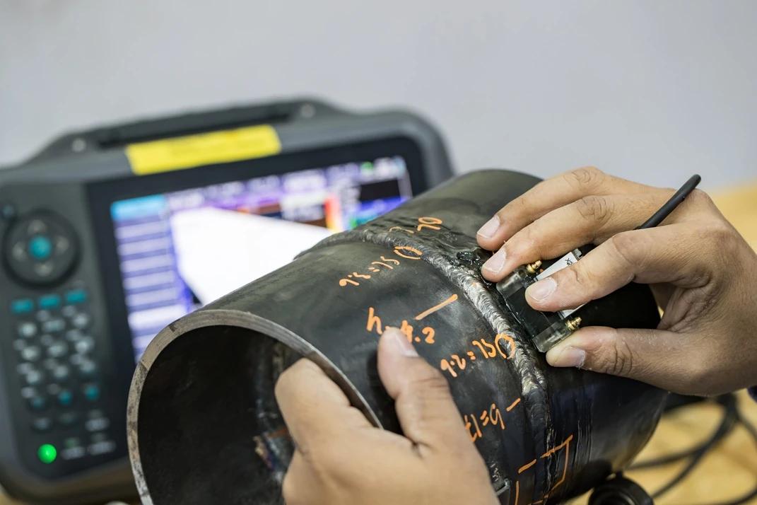
Ultrasonic testing and gauging
Ultrasonic methods support thickness confirmation, local condition assessment and flaw detection where visual inspection indicates wall loss, cracking risk or structural concern.
Corrosion assessment
Inspection is tied to corrosion mechanism, exposure, local geometry and remaining wall condition so the next technical decision is based on measured condition rather than surface appearance alone.
NDT methods selected by inspection requirement
The objective is to apply the correct method to the condition identified and produce a result that can be used directly for survey, engineering assessment or repair planning.

UT, UTG, MPI and PT
Conventional methods are applied where inspection identifies corrosion, wall loss, weld concern or cracking risk. Selection is based on defect mechanism and what has to be confirmed in the field.
Advanced methods selected by inspection requirement
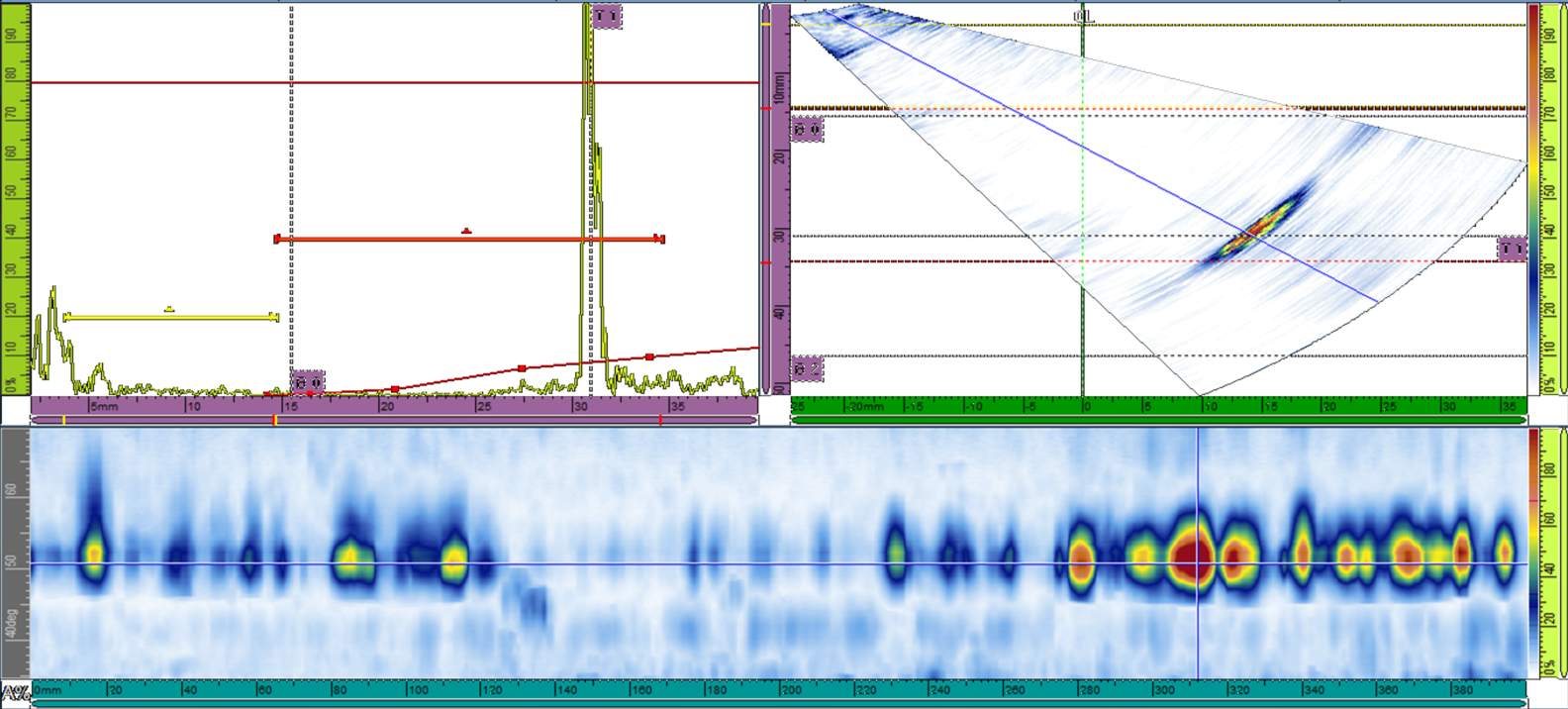
PAUT, TOFD, eddy current, guided wave and corrosion mapping are used where geometry, coverage, sizing accuracy or flaw characterisation require more than conventional methods.

Radiographic testing under controlled conditions
Radiographic testing is used where specified or required for defect evaluation. Compact systems such as SCAR support deployment where access and safety constraints have to be managed carefully.
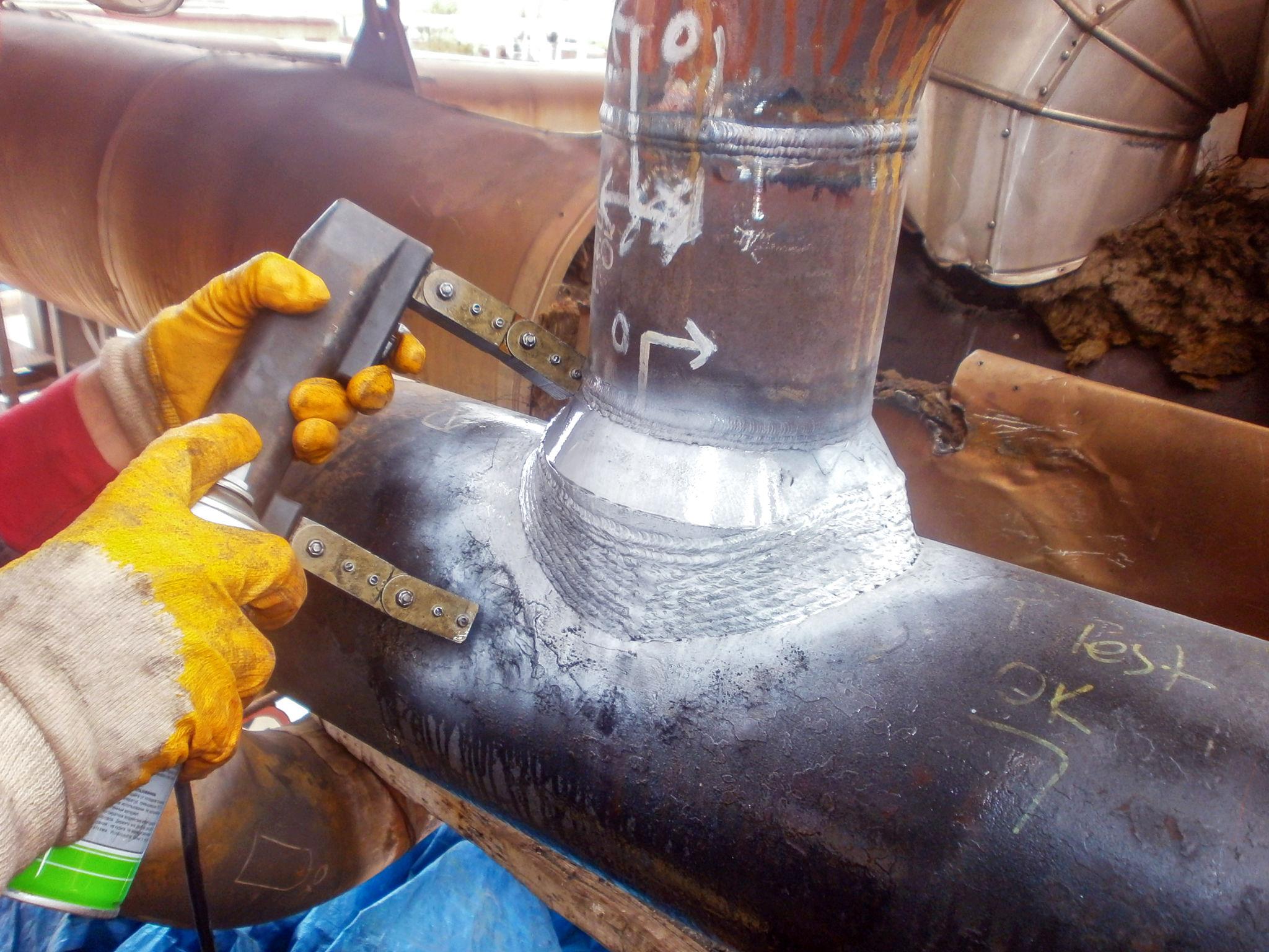
MPI on structural details and connection points
MPI supports crack detection on ferromagnetic components, welds, flange connections and other details where surface and near-surface indications have to be confirmed clearly.

PT for surface-breaking indications
Penetrant testing is used where material type, surface condition and expected indication type make it the correct method for local crack detection and follow-up examination.
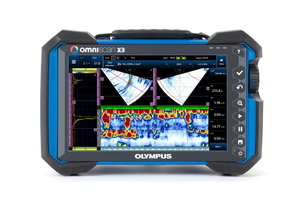
Advanced method selection by requirement
Advanced NDT is deployed where scope, geometry, defect mechanism and acceptance criteria justify the method and reporting depth. PAUT scan output strengthens interpretation where conventional methods alone are insufficient.
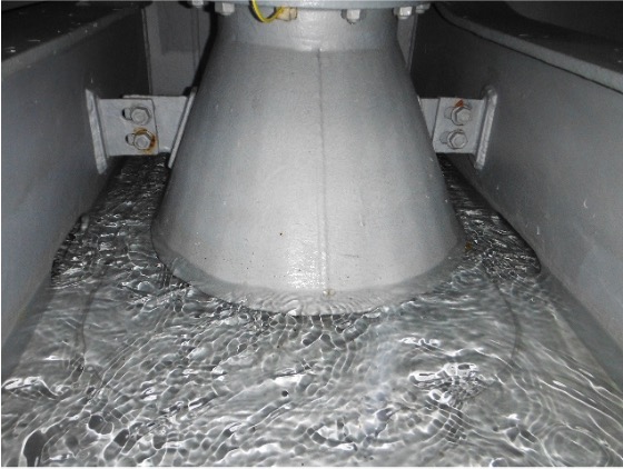
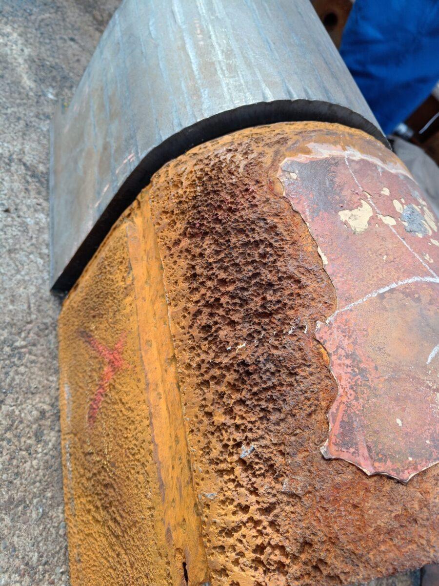
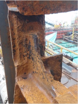
Thickness gauging confirms whether surface appearance reflects actual wall loss
Offshore steel can appear serviceable while section loss, pitting, grooving or local wastage has already moved the area into escalation or repair territory. Inspection has to separate cosmetic condition from actual remaining wall thickness and structural consequence.
MMurphyEx supports condition assessment where corrosion type, wall loss, pitting severity and coating condition are identified, measured and reported to support structural integrity and repair scope.
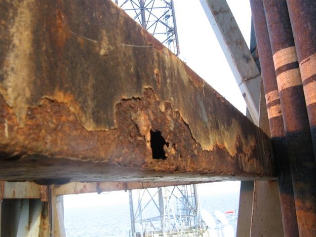
Corrosion mechanism awareness
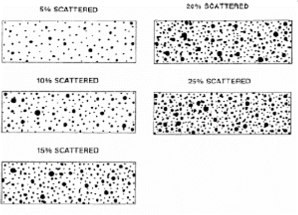
General corrosion, pitting, grooving, edge effects and local coating failure do not carry the same structural consequence or inspection response.
Localised material loss
Pitting and concentrated wastage often drive additional thickness measurement, tighter inspection coverage and clearer repair definition than broad but uniform surface deterioration.
Escalation where deterioration requires it
Inspection extent can increase quickly where deterioration patterns indicate deeper local loss, wider spread or reduced confidence in the initial examination.
Thickness measurement data supporting survey decisions, repair scope and engineering assessment
Ultrasonic thickness measurement is often the control point between visual concern and a measurable decision. Where corrosion, wastage or suspected section loss is identified, inspection moves from observation into structured measurement, local confirmation and mapping of the affected area.

Field measurement
Thickness measurement is carried out against the actual structure, coating condition, access limitations and the local deterioration pattern identified during inspection.
Mapped condition data
Results can be organised into defined measurement patterns and local thickness maps so steel loss and extent are clear to the client, surveyor and repair team.
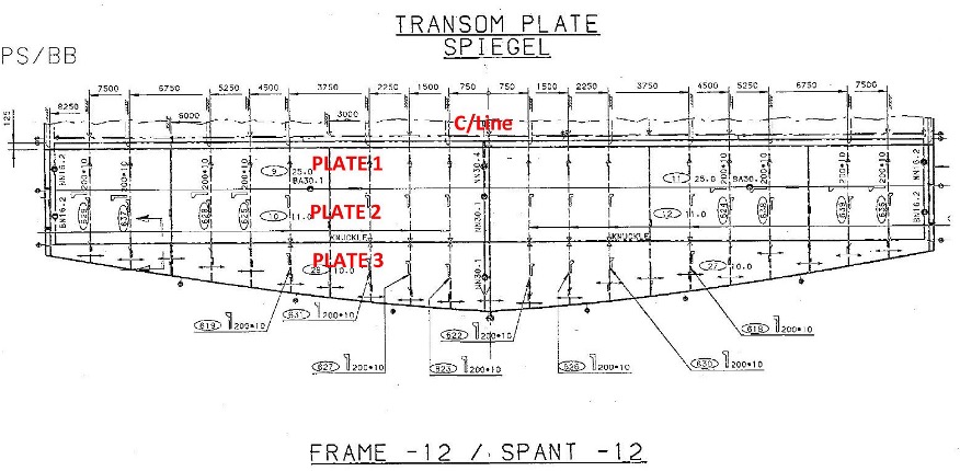
Structure-based thickness measurement
Plate geometry, framing, local support detail and surrounding structure all influence where thickness measurements are taken and how the result is interpreted.
Identify condition
Close visual inspection defines the local concern, coating condition, corrosion spread and where escalation is warranted.
Measure properly
Thickness points, local follow-up and additional gauging are applied to represent the condition accurately.
Interpret against criteria
Readings are assessed against original thickness, allowable loss, local condition and the applicable survey or engineering criteria.
Define outcome
Outcome supports continued service assessment, further NDT, repair scope, steel renewal planning or verification after repair.
Inspection support beyond hull and tank condition
NDT support is not limited to steel plate wastage. Offshore assets also require controlled inspection of welded pipework, pressure-containing systems, local structural details and connection points where crack detection, weld assessment or condition confirmation is required.
Pipe weld and connection inspection
Inspection supports local weld condition assessment, crack detection, verification after remediation and technical follow-up where service condition or integrity concern indicates examination.

Pressure system inspection support
High-pressure and critical service pipework requires appropriate method selection, controlled execution and reporting that links the finding to a technical assessment.

Offshore inspection beyond primary structures
Where scope extends beyond plate condition into risers, piping runs and connection details, inspection remains structured, controlled and aligned to defined acceptance criteria.
NDT support for SPS, intermediate surveys and structural inspection
Special Periodic Survey work creates pressure around preparation, access, close visual inspection, condition grading, measurement extent and repair prioritisation. This is where NDT becomes critical to survey completion, repair definition and technical assessment.
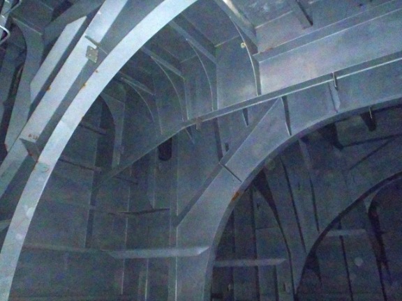
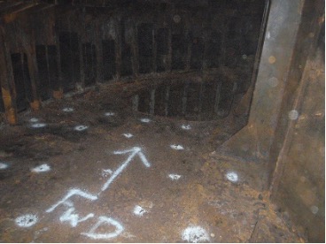
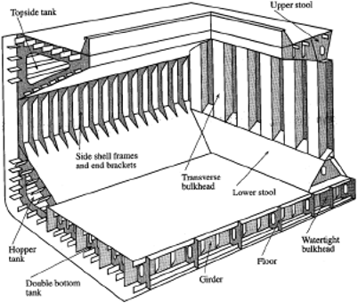
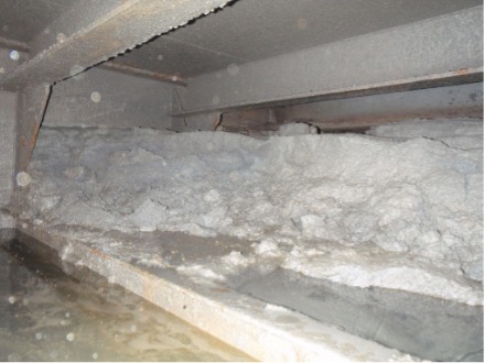
Void spaces and internal condition
Inspection support includes internal condition assessment, wastage identification, local escalation and condition recording in spaces where deterioration is not visible externally.
Close visual inspection support
Close visual inspection establishes whether thickness confirmation, additional NDT or repair planning is required before the area is assessed by the attending surveyor or client team.
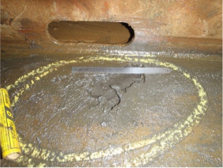
Preparation before NDT
Condition, local cleaning and preparation have a direct effect on inspection quality, measurement confidence and the credibility of the final result.
Inspection focus areas
Survey windows often require prioritised inspection of critical locations, suspect structure and known deterioration zones rather than broad undirected checking.
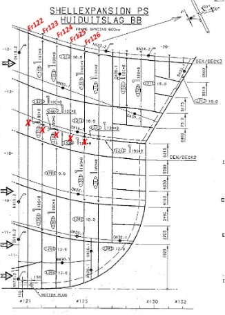
Structure-led planning
Plate, frame and detail layouts support consistent reference, reporting clarity and cleaner communication between inspector, client team and attending surveyor.
Inspection findings have to support a clear technical assessment
Inspection only has value when the finding is translated into a clear technical position. That may mean acceptable condition, additional examination, repair planning, steel renewal, engineering assessment or verification after repair before acceptance.
Condition is within the applicable acceptance criteria and can be recorded as acceptable for continued service or survey review.
Condition indicates local concern, additional thickness measurement, expanded NDT, engineering assessment or a tighter inspection pattern before final assessment.
Measured condition and structural consequence indicate repair planning, steel replacement, controlled remediation or a survey hold-point pending further action.

Inspection supporting repair planning and verification
A properly run NDT scope does not stop at the test itself. It supports repair definition, steel renewal extent, verification after remediation and the documentation required for survey or engineering review.
MurphyEx supports that chain from field condition assessment through reporting, repair support and reinspection where specified.
Discuss NDT, SPS or structural inspection support
MurphyEx supports offshore drilling and production assets with inspection planning, close visual inspection, conventional and advanced NDT, corrosion assessment, thickness measurement, repair support and verification after repair where specified.